¶ FM Radio Kit - Tall Boy Project
¶ Overview
The Tall Boy is a 3D printed tabletop enclosure for the UnderBaked FM Radio Kit. It turns the solderless FM radio electronics into a finished retro-inspired radio with a front speaker grill, tuning knob, volume knob, power switch, LED indicator, internal antenna routing, and rear battery compartment.
This guide walks through the assembly of the Tall Boy enclosure using step-by-step reference images. Most images include arrow overlays to highlight the parts being installed or adjusted.
For print preparation and slicer setup, see the Tall Boy Printing Guide.
If you are designing your own enclosure, this guide can also be used as a reference for board placement, switch and knob alignment, speaker mounting, antenna routing, and battery pack placement.
¶ Requirements
¶ Included In Kit
- FM Radio Kit circuit board
- Speaker driver, such as Multicomp Pro MP001193 or equivalent
- 3×AA battery holder, such as MYOUNG BH-AA-B1AJ017 or equivalent
- Power switch
- LED power indicator
- Wire antenna
- M3 screws, nuts, and washers
¶ Not Included
- Printed Tall Boy enclosure parts
- Screw Drivers (listed below)
- 3× AA batteries
- PLA-compatible adhesive for the battery compartment and feet
¶ Recommended Tools
- 2.5 mm hex driver or T-handle, with a shaft at least 130 mm long
- Phillips #1 screwdriver
- Phillips #2 screwdriver
- Needle-nose pliers
- Tweezers
- Soft cloth or mat to avoid scratching printed parts
The optional UnderBaked Driver Kit includes the long 2.5 mm hex, PH1, and PH2 bits used for this build.
¶ Hardware Checklist
The Tall Boy build uses the following hardware:
| Item | Quantity | Used For |
|---|---|---|
| M3 × 4 mm flush screws | 10 | Antenna clip, battery pack, battery door, final enclosure screws |
| M3 × 6 mm screws | 9 | FM radio board, power indicator, speaker bracket |
| M3 × 8 mm screws | 3 | Speaker mounting bracket |
| Potentiometer nuts | 2 | Tuning and volume controls |
| Potentiometer spring washers | 2 | Tuning and volume controls |
| Switch nut | 1 | Power switch |
| Switch spring washer | 1 | Power switch |
Verify screw lengths before final assembly. A screw that is too long may damage printed parts or interfere with internal components.
¶ Safety Notes
- Verify polarity before connecting any battery or power lead. The supplied connectors should already be wired correctly, but it is still worth checking before first power-on.
- Do not force connectors, knobs, switches, or enclosure parts.
- Disconnect power before adjusting internal wiring.
- Keep batteries away from heat, puncture risk, and short circuits.
- Before first power-on, turn the volume control fully counter-clockwise to minimum.
For full safety guidance, see FM Radio Kit Safety.
¶ Procedure
¶ Step 1: Glue battery compartment
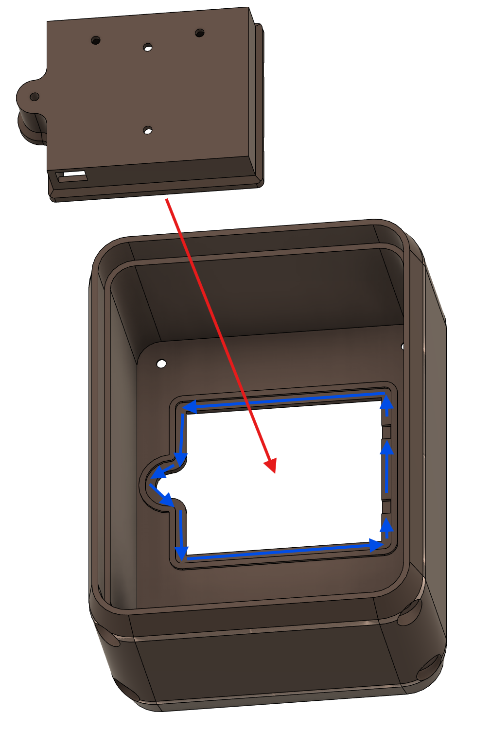
Glue the battery compartment (Case - AA Battery Box) to the enclosure (Case) part shown. Blue arrows indicate where to place glue.
¶ Step 2: Glue feet to case
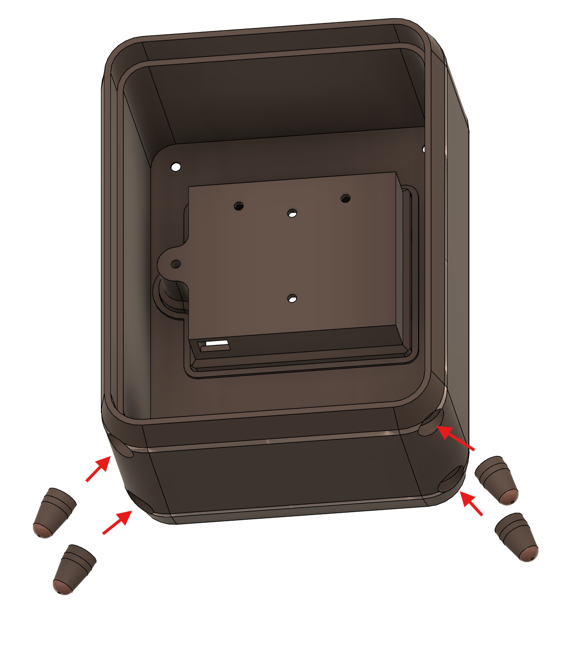
Glue the feet to the case in the indicated positions.
Once the battery box and feet are glued in place, set the case aside and allow the adhesive to cure. While the adhesive sets, you can begin assembling the internal core (Grill Body) of the radio.
¶ Step 3: Install FM radio board
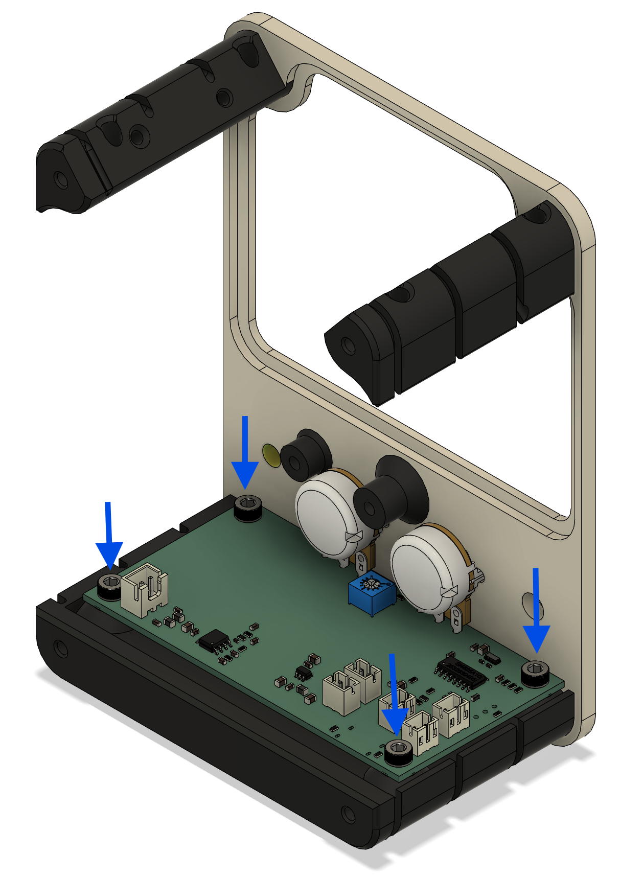
Place the FM radio board into the grill body and secure it using four M3 × 6 mm screws.
The tuning and volume potentiometers pass through the front panel. Secure them using the supplied spring washers and nuts.
¶ Step 4: Install grill and speaker mount
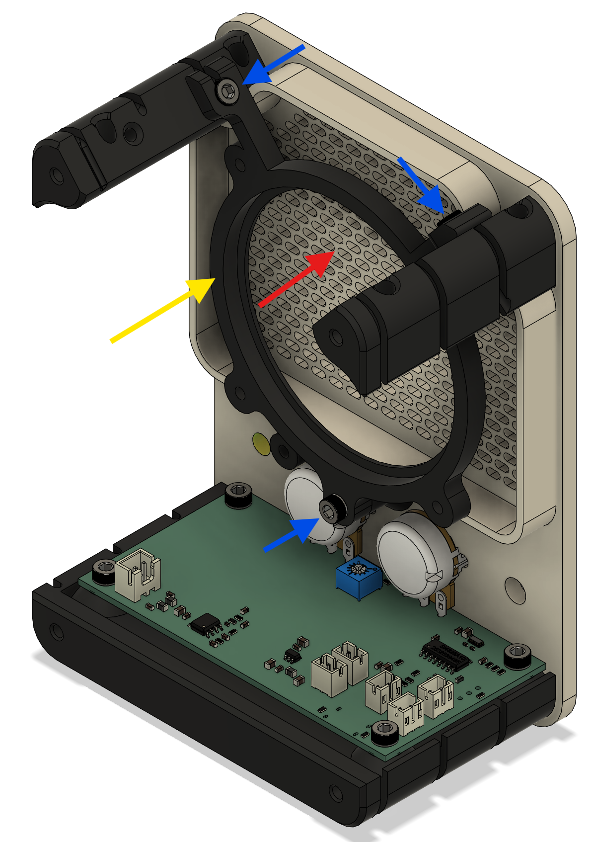
Position the front grill in the grill body, then place the speaker mounting bracket behind it.
The grill is a friction fit and is held in place by the speaker mounting bracket. Secure the speaker mounting bracket to the grill body using three M3 × 8 mm screws.
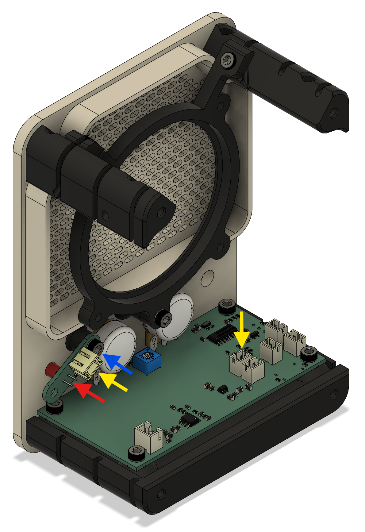
¶ Step 5: Fit power indicator
Install the power indicator component in the highlighted location using one M3 × 6 mm screw. Connect the power indicator light to J7, one of two AUX connectors.
¶ Step 6: Install power switch
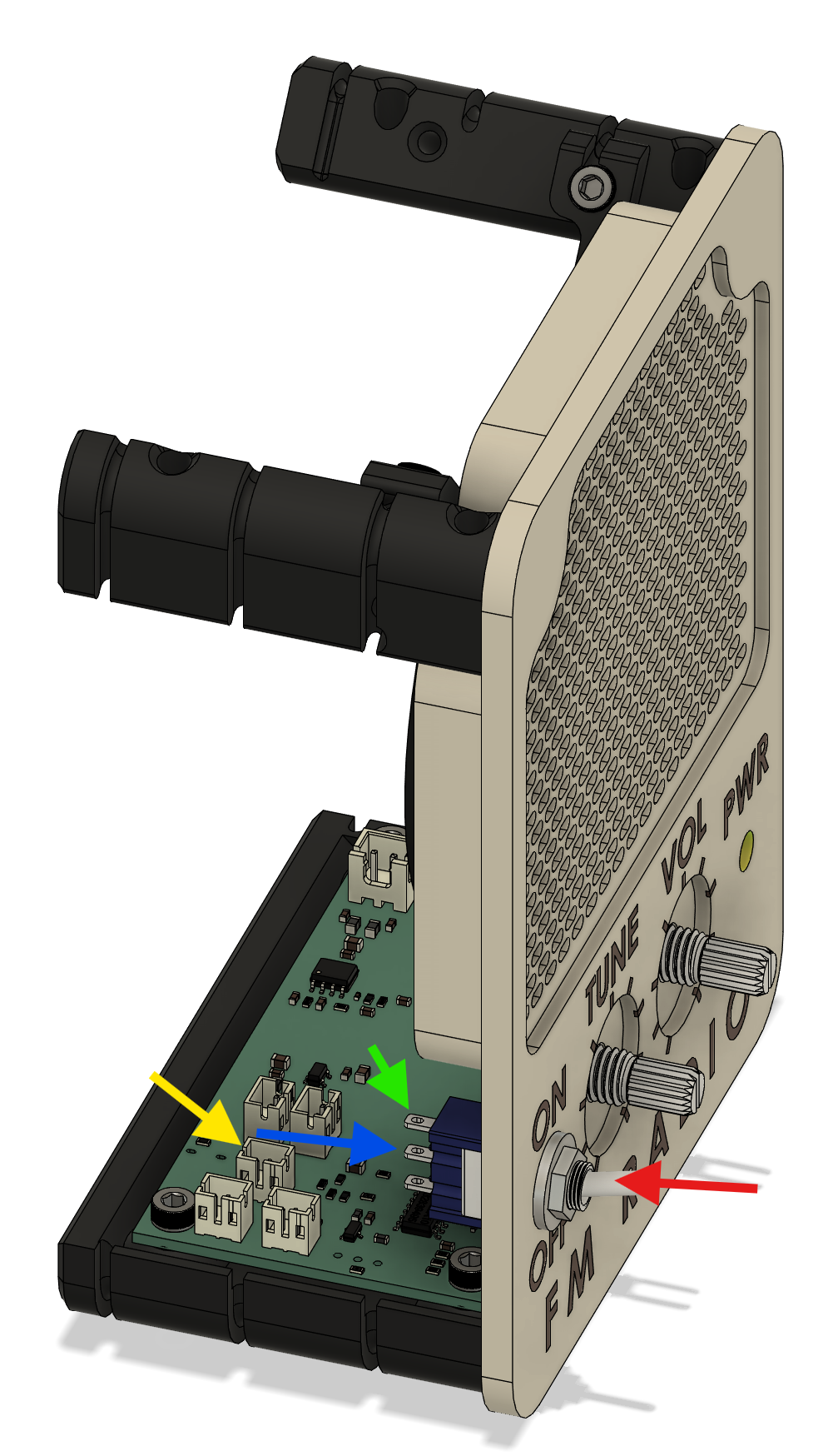
Install the power switch and confirm that it moves freely.
The switch is secured from the front using its spring washer and nut. The switch has three terminals, but only two are used. For the intended orientation, the unused terminal should face upward.
Connect the switch lead to J4, marked Switch.
¶ Step 7: Install knobs
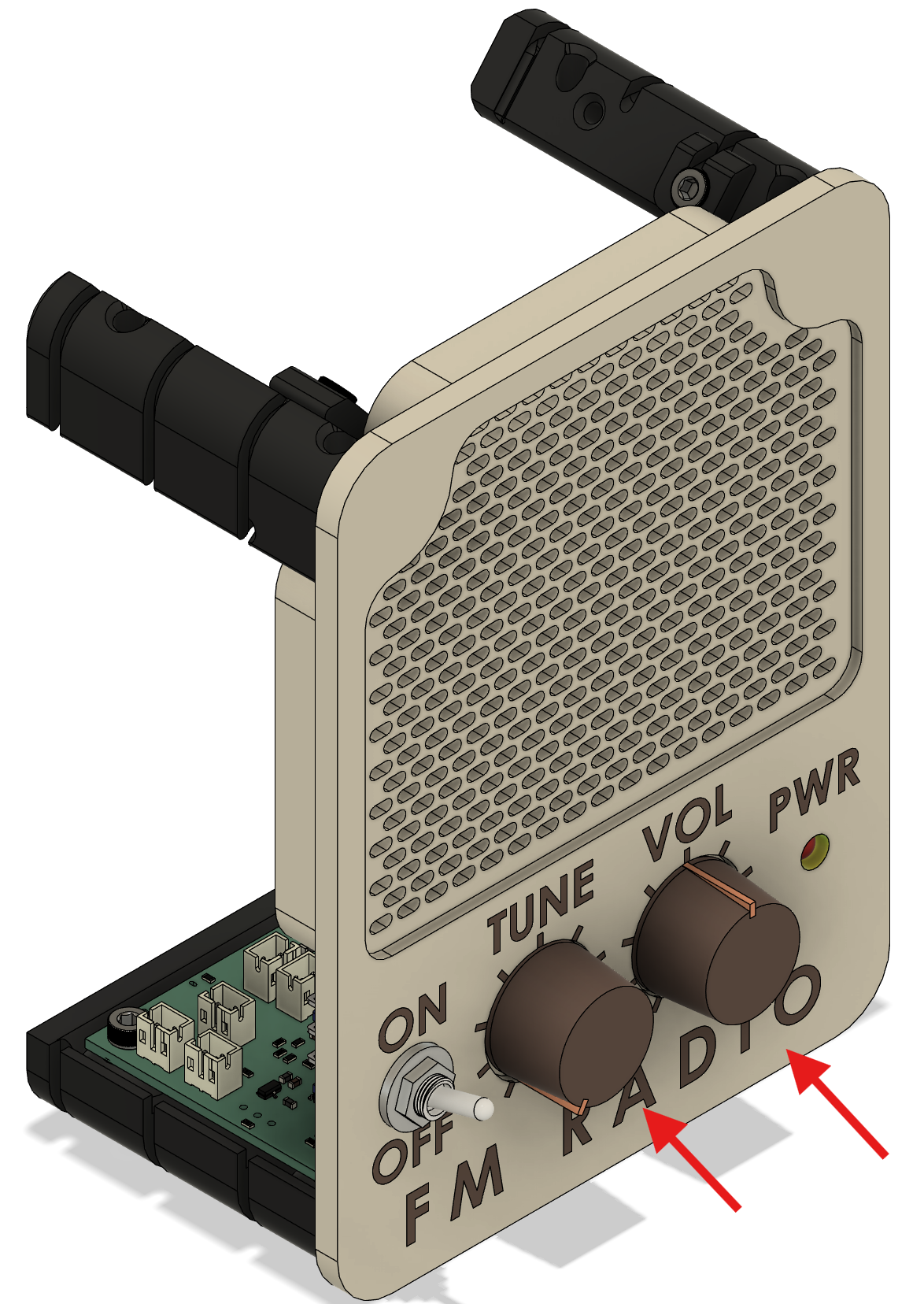
Press-fit the knobs onto the tuning and volume shafts.
The fit should be firm, but not painful to install. If the knobs require excessive force, inspect them for print artifacts. If needed, reprint the knobs slightly larger on the X and Y axes, by approximately 0.1 mm to 0.2 mm.
¶ Step 8: Install speaker
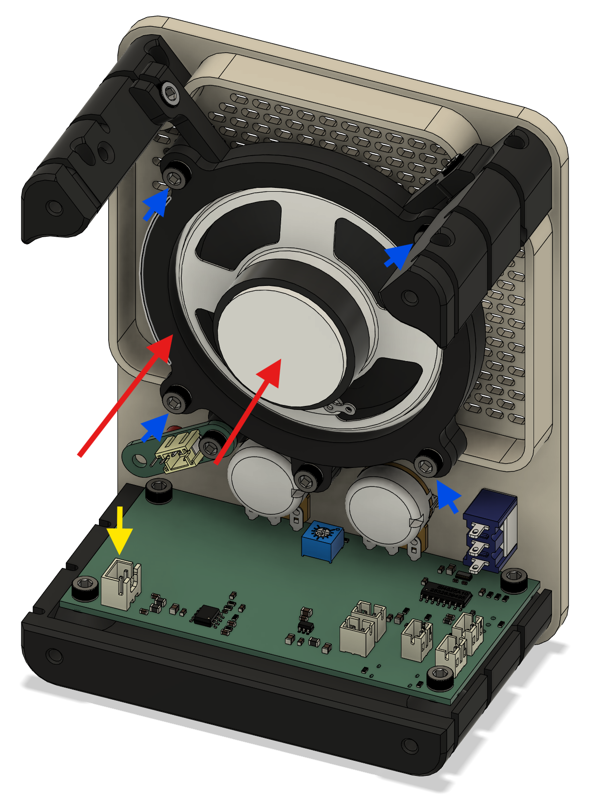
Route the speaker wire and connector through the center opening of the retaining bracket. Secure the retaining bracket to the speaker mounting bracket using four M3 × 6 mm screws.
Connect the speaker cable to J3, SPK.
¶ Step 9: Route and fit antenna
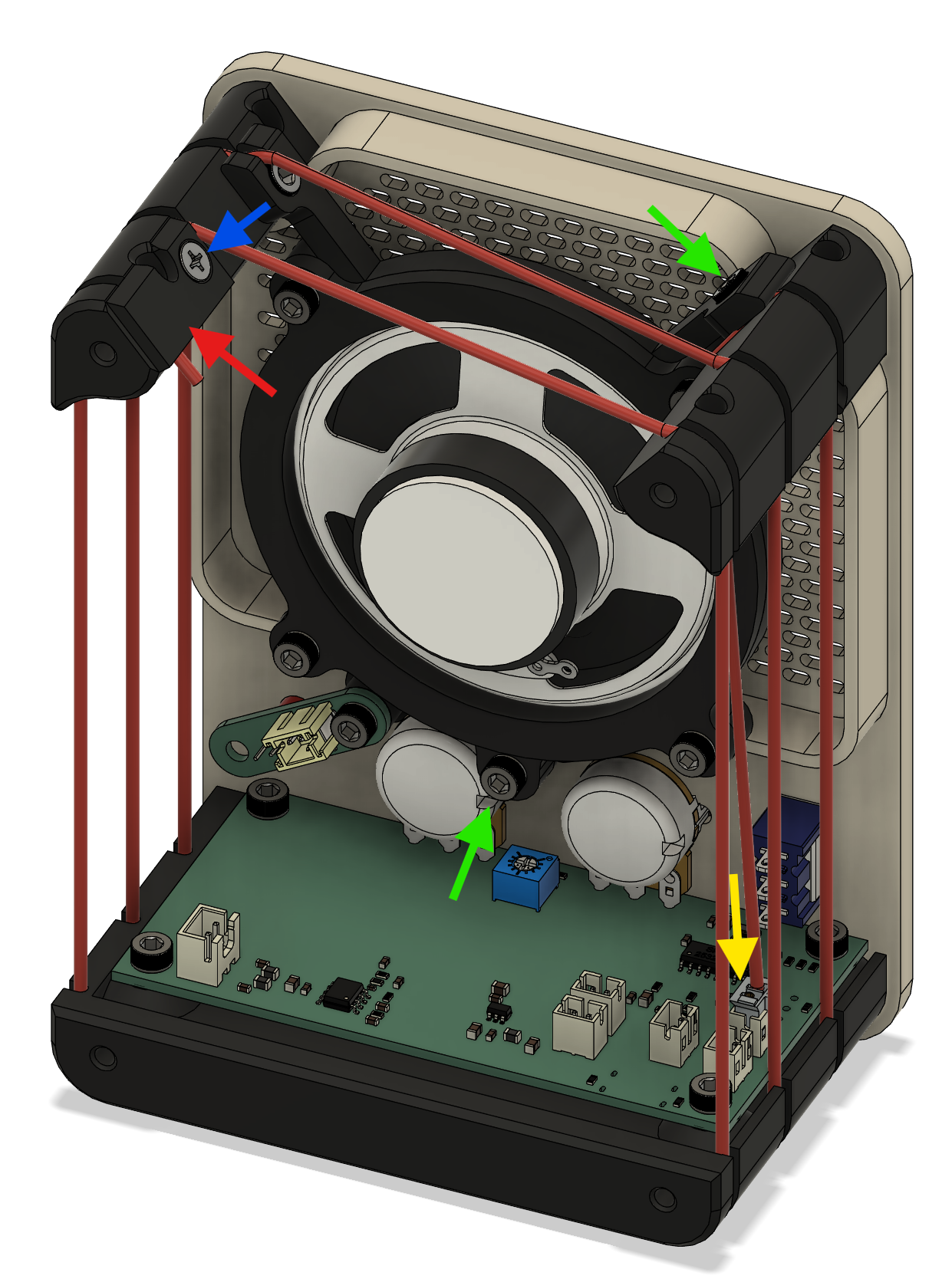
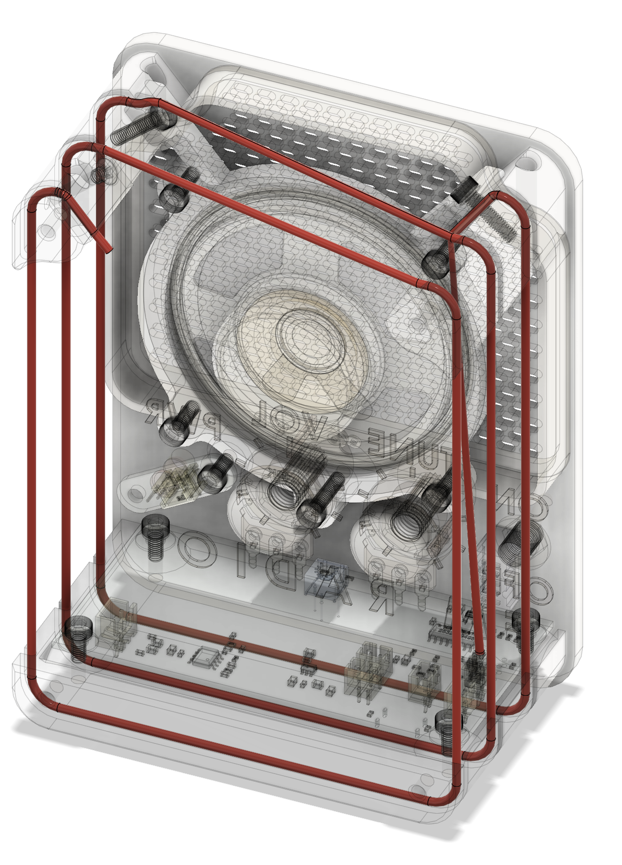
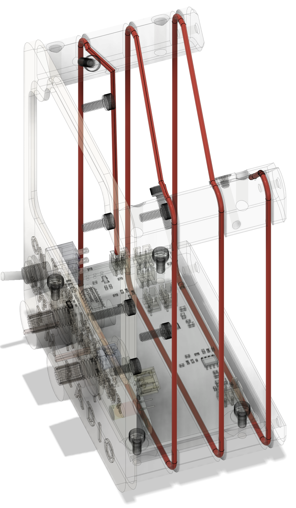
Install and route the antenna as shown in the images below.
This step is a little finicky. You may need to loosen the screws holding the speaker bracket so the antenna wire can sit correctly in the routing groove.
Connect the antenna to J6, marked ANT. From there, route the wire upward into the groove covered by the speaker mount. Continue looping the antenna around the grill body, starting near the front and working toward the back.
The antenna wire should finish in the rear groove, where it is held in place by the antenna clip and one M3 × 4 mm flush screw.
¶ Step 10: Install battery pack
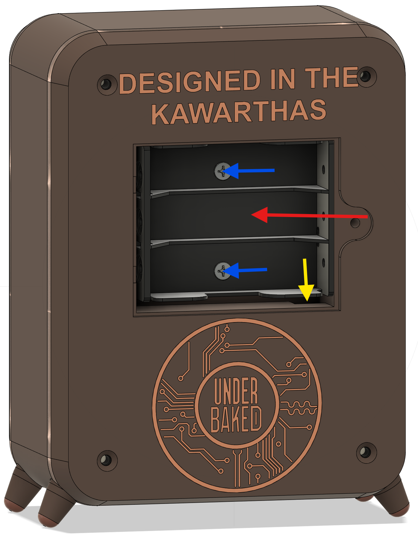
Place and secure the battery pack in the intended compartment using two M3 × 4 mm flush screws.
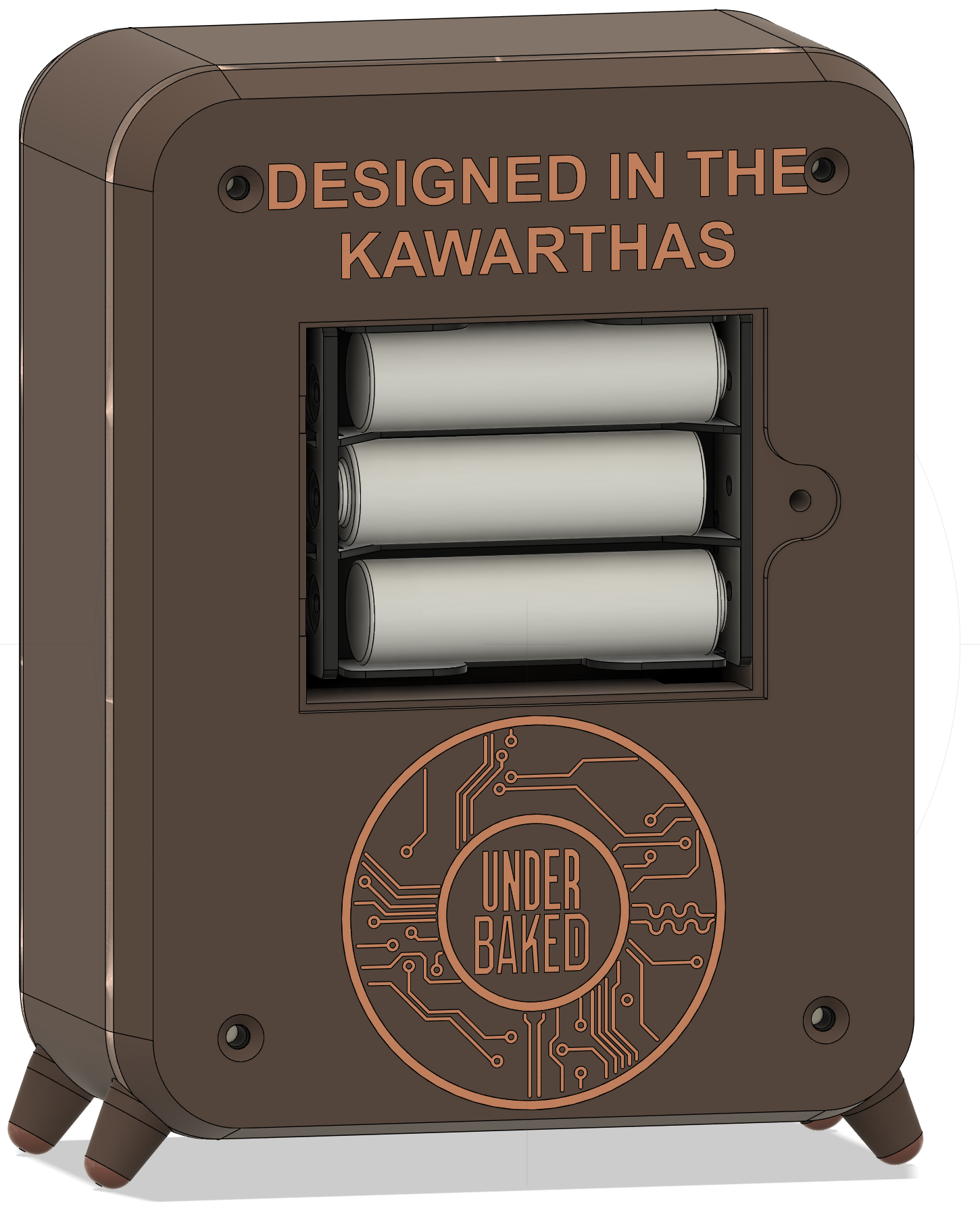
¶ Step 11: Install batteries
Install batteries with correct polarity.
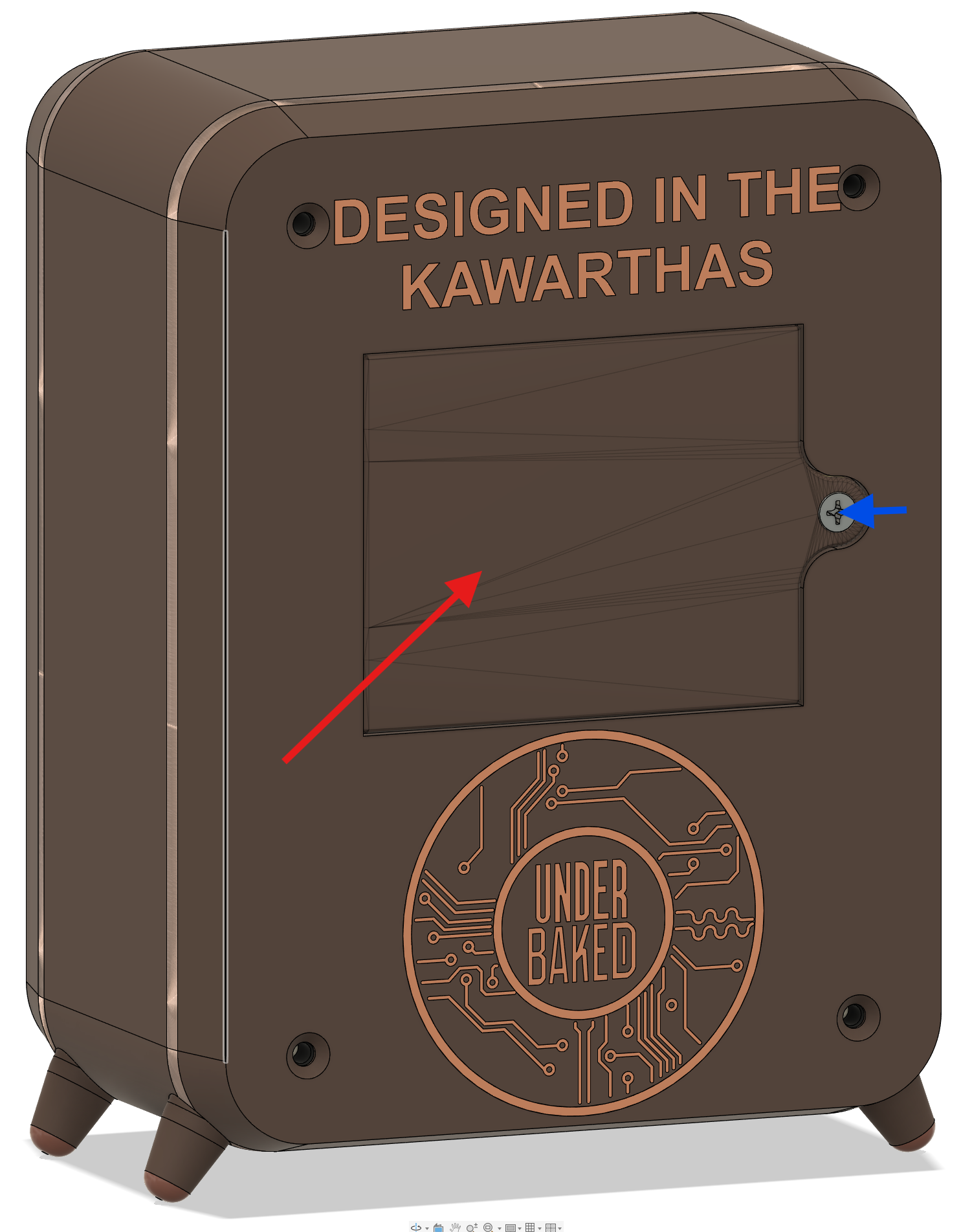
¶ Step 12: Fit battery door
Close and secure the battery door using a one M3 × 4 mm flush screw.
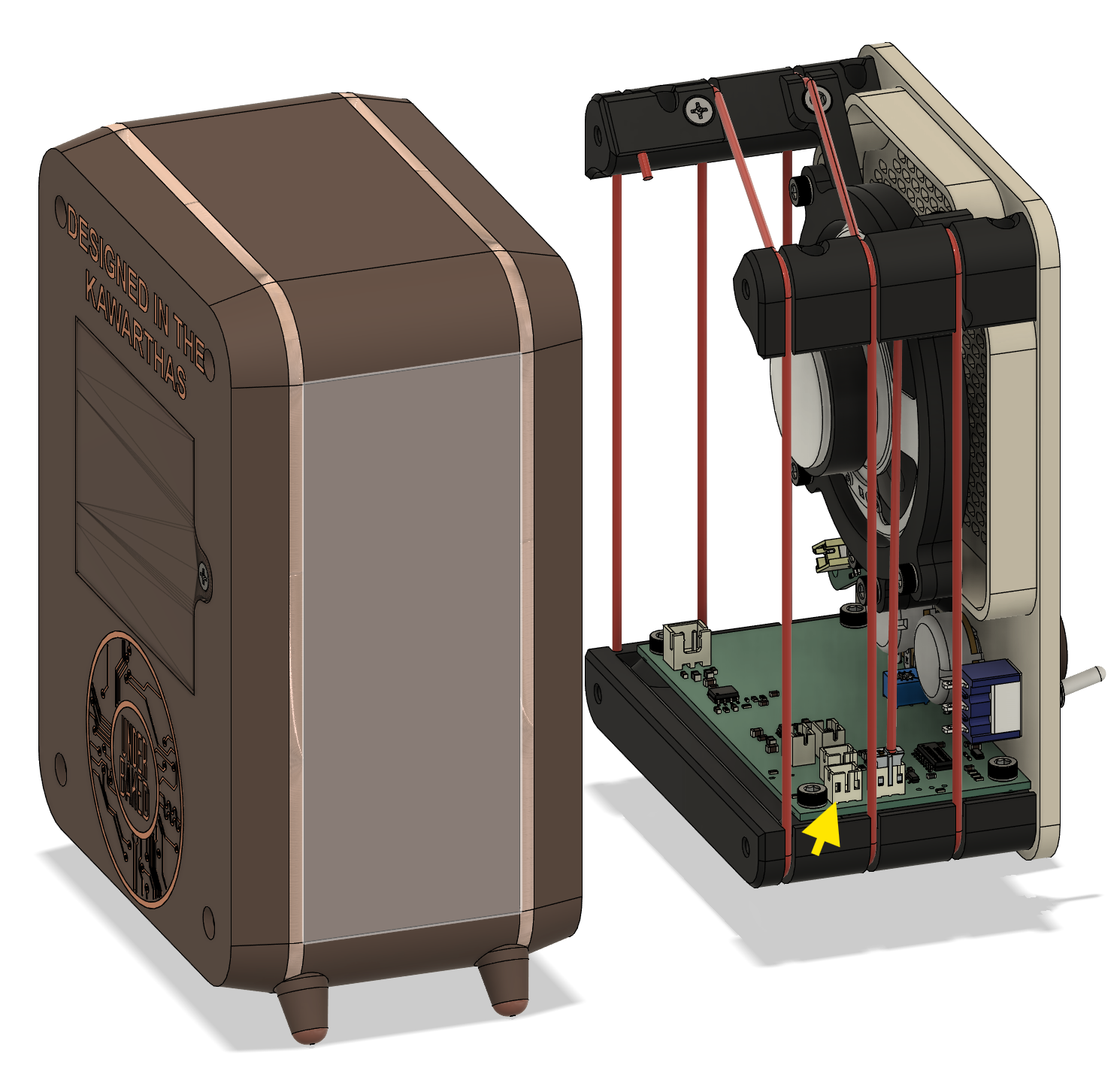
¶ Step 13: Final enclosure assembly
Join the outer case and inner radio assembly.
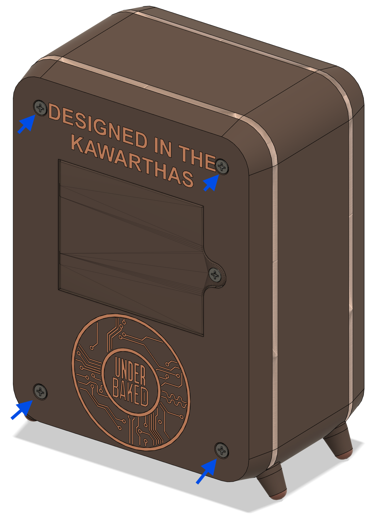
Before fully closing the enclosure, connect the battery lead to J1, marked Power, and briefly check that the radio powers on. After confirming basic power operation, finish closing the enclosure and install the final M3 × 4 mm flush screws.
¶ First power-on check
Before regular use:
- Verify battery polarity one final time.
- Confirm no wires are pinched by the enclosure.
- Turn volume low, then power on.
- Check indicator behavior and basic radio tuning.
¶ Troubleshooting
¶ Radio does not power on
- Re-check battery orientation and battery contact pressure.
- Confirm switch installation and travel.
- Open case and confirm no disconnected leads.
¶ Weak or no reception
- Re-check antenna routing and connection.
- Reposition the antenna away from dense wiring bundles.
- Test in another room or near a window.
¶ Distorted or no sound
- Confirm speaker connection and seating.
- Check knob alignment and volume setting.
- Re-open enclosure and inspect for pinched speaker wires.
¶ Parts do not fit cleanly
- Remove and re-seat the affected part; do not force.
- Clean print artifacts on mating edges.
- Verify that the correct Tall Boy part orientation is used.
¶ Revision Notes
- 2026-07-02: Initial Tall Boy project page created with step-by-step assembly images.
- TODO: Add printable file links and complete hardware specifications.
- TODO: Add direct printable file links.
- TODO: Verify final screw quantities against packaged hardware.