¶ Li-Ion Boost Charger - Assembly Instructions
¶ Requirements
¶ Tools Needed
- No tools required
- Multimeter (REQUIRED for voltage verification)
¶ Skills Required
- Ability to connect connectors
- Following step-by-step instructions
- Basic understanding of battery safety
¶ Before You Begin
⚠️ CRITICAL: Read the Safety Guidelines completely before starting.
- Read all instructions completely before starting
- Understand lithium-ion battery hazards
- Organize components using the Bill of Materials
- Prepare a clean, well-lit workspace
- Have fire safety equipment nearby
¶ Assembly Procedure
Note: All connections are optional. Connect only the modules needed for your desired configuration.
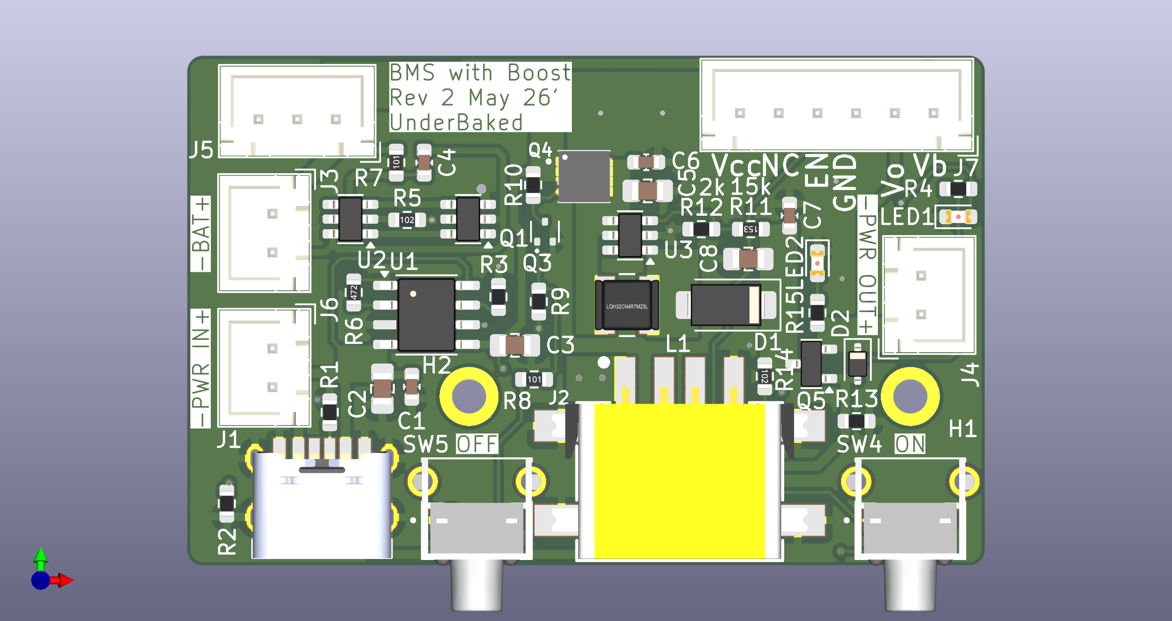
Top view showing component locations and connectors
¶ Step 1: Identify Components
Locate the following on your Li-Ion Boost Charger board:
- USB-C Port (J2): Center-bottom - for charging input
- Power Connectors: J1, J3, J5, J7 - JST connectors on left side
- J1: Power output
- J3: Battery connection
- J5: Power input
- J7: Additional power connection
- Power Switches:
- SW4 (labeled "ON"): Right side
- SW5 (labeled "OFF"): Center-left
- Note: Switch configuration customizable when ordering
- LED Indicators: LED1, D1, D2 - for power and charging status
- Test Points: Vcc, GND, Vb - for voltage monitoring
- QR Code (QR1): For quick documentation access
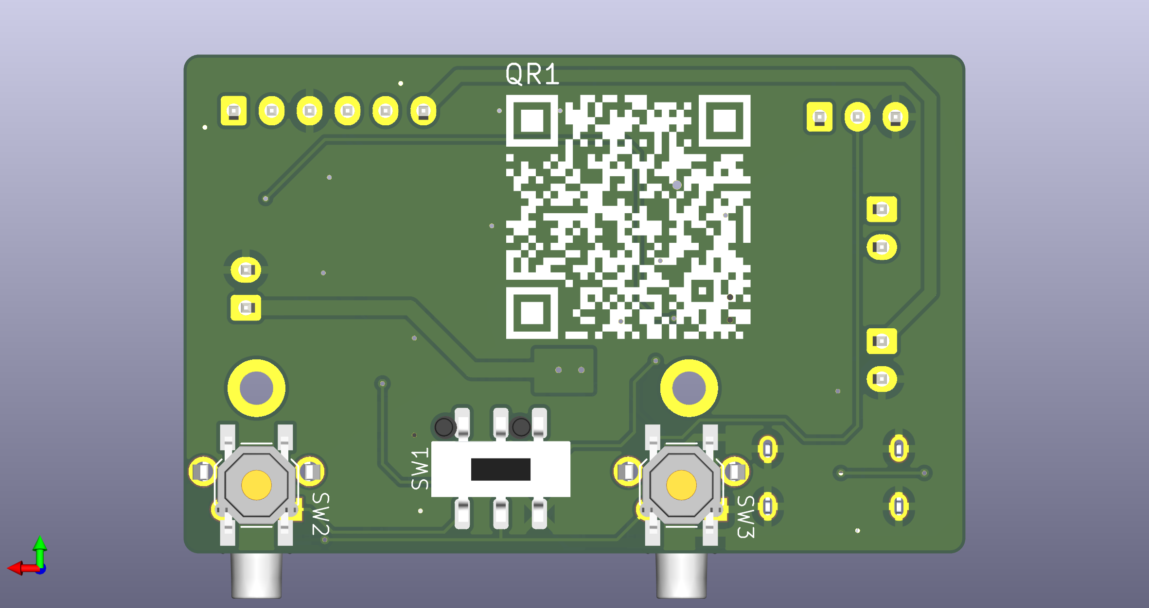
Bottom view showing connector details
Safety Note: Handle modules carefully to avoid damage to components and connectors.
¶ Step 2: Pre-Connection Testing (REQUIRED)
Before connecting any battery:
- Use a multimeter to verify all test points
- Check for any shorts between Vcc and GND
- Inspect all connectors for damage or debris
- Verify switch positions (if switches are installed)
Safety Note: This step is critical for preventing battery damage or fire hazard.
¶ Step 3: Connect Battery (If Required)
⚠️ CRITICAL SAFETY: Read this entire step before proceeding.
- Verify battery type and voltage - must be compatible Li-ion cell
- Check battery connector - identify positive (+) and negative (-) terminals
- Locate J3 (BAT+ connector) on the left side of the board
- Triple-check polarity:
- Match battery red wire to board + marking
- Match battery black wire to board - marking
- Verify connector orientation
- Align connector - JST connector should fit only one way
- Insert slowly - press firmly until connector clicks
- Verify LEDs - status indicators should illuminate if battery has charge
Safety Note:
- NEVER force a connector
- Battery connector IS keyed, but always verify polarity
- Reversed polarity can cause fire or explosion
- If unsure, DO NOT CONNECT - seek assistance
¶ Step 4: Connect USB-C Charging Cable
- Locate the USB-C port (J2) at the center-bottom of the board
- Connect a USB-C cable from a 5V USB power source
- Charging LED should illuminate when battery is connected and charging
Safety Note:
- Use only 5V USB power sources
- Do not charge damaged or swollen batteries
- Monitor first charging session
¶ Step 5: Connect Power Output (Optional)
- Identify connector J1 (PWR_OUT) on the left side
- Connect your output device cable
- Verify output voltage at test points (should read ~5V when active)
Safety Note: Do not exceed maximum output current rating.
¶ Step 6: Configure Power Switches (If Installed)
Note: Switch configuration is customizable when ordering. Your board may have:
- Through-hole switches (SW2, SW3 on bottom)
- Surface-mount switches (SW4, SW5 on top)
- No switches (always-on configuration)
If switches are installed:
- SW4 (ON switch): Typically controls power output enable
- SW5 (OFF switch): Typically controls charging/system disable
- Test switch operation before final assembly
Note: Refer to your specific board configuration for switch functions.
¶ Step 7: Connect Additional Power Sources (Optional)
For advanced configurations:
- J5 (PWR_IN): Alternative power input
- J7: Additional connection (refer to schematic)
Safety Note: Do not connect multiple power sources simultaneously without understanding circuit design.
¶ Step 8: Visual Inspection
Before final operation:
- Verify all desired connections are fully seated and clicked
- Check polarity markings on battery connector
- Confirm no exposed conductors or damage
- Verify LED indicators are functioning
- Check test point voltages with multimeter:
- Vb should read battery voltage
- Vcc should read regulated voltage
- GND should be common ground
- Ensure switches are in desired positions
Safety Note: If anything appears damaged or incorrect, disconnect immediately.
¶ Step 9: Initial Testing (WITHOUT BATTERY)
TODO: Testing procedures without battery connected
- Connect input power (if not already connected)
- Measure voltages at test points with multimeter
- Verify LED indicators (if present)
- Check for any unusual heating
- Measure output voltage range
Note: You can disconnect and reconnect modules at any time to change configuration.
¶ Step 10: Battery Testing (If Battery Connected)
⚠️ WARNING: Only proceed if initial testing passed successfully.
TODO: Battery connection and testing procedures
- Connect known-good battery within specifications
- Monitor battery voltage during initial charge
- Monitor module temperatures
- Be prepared to disconnect battery immediately if issues occur
- Never leave charging battery unattended
Note: Battery connection is optional. System can be tested and used without battery attached.
¶ Next Steps
- If the charger doesn't work properly, see Troubleshooting
- Review Safety Guidelines for operational safety
- For questions, visit Support
Last Updated: TODO
Revision: See Revision Notes