⚠️ Before troubleshooting:
- Disconnect battery
- Disconnect power supply
- Allow components to cool
- Review Safety Guidelines
- Visual Inspection: Check for loose connections or damaged components
- Polarity Check: Verify all polarized components and connections
- Power Supply: Confirm correct voltage and current capability
- Module Configuration: Verify modules are correctly installed
- Multimeter Testing: Measure voltages at key test points
Symptoms: Circuit appears dead, no indication of power
Possible Causes:
- Reversed input power polarity
- Faulty power supply
- Blown protection fuse/component
- Short circuit
- TODO: Additional causes
Solutions:
- Verify input power supply voltage and polarity with multimeter
- Check for short circuits between power rails
- Test protection components
- TODO: Additional solutions
Safety Note: Never apply battery power until input power tests successfully.
Symptoms: Battery connected but charge current is zero or very low
Possible Causes:
- Battery already fully charged
- Battery protection circuit activated
- Incorrect charge current setting resistors
- Faulty charging IC
- Battery below minimum voltage (deep discharge)
- TODO: Additional causes
Solutions:
- Measure battery voltage (should be within TODO range)
- Verify charging IC enable pin state
- Check charge current sense resistor values
- Measure voltage at key IC pins per datasheet
- TODO: Additional solutions
Safety Note: If battery is swollen, damaged, or leaking, do not attempt to charge. Dispose of properly.
Symptoms: Charging current too high or too low
Possible Causes:
- Incorrect module configuration
- Loose connection
- Damaged component
- TODO: Additional causes
Solutions:
- Verify module configuration settings
- Recalculate expected charge current: TODO formula
- Check all connections are secure
- TODO: Additional solutions
Symptoms: Output voltage not at expected 5V
Possible Causes:
- Incorrect feedback resistor values
- Faulty boost IC (U3)
- Insufficient input voltage from battery
- Inductor saturation due to overcurrent
- Output overload
- Boost converter disabled
Solutions:
- Measure input voltage at Vb test point (should be TODO V from battery)
- Measure output at test point Vcc (should be ~5V)
- Check if output load is within current rating (TODO mA max)
- Verify boost enable signal if applicable
- Test with lighter load to rule out overload condition
- Check inductor L1 for damage or overheating
- Measure voltage at U3 pins per datasheet specifications
Symptoms: Power switches SW4 (ON) or SW5 (OFF) have no effect
Possible Causes:
- Switch configuration not as expected (customizable when ordering)
- Mechanical switch failure
- Circuit always enabled/disabled regardless of switch
- Switch not fully actuated
Solutions:
- Verify your board's switch configuration - switches are customizable
- Press switches firmly - should feel positive click
- Check board documentation for your specific switch configuration
- Test continuity across switch terminals with multimeter (power off)
- If board has alternative switches (SW2/SW3 on bottom), check those instead
- Some configurations may not use switches (always-on)
Note: Your board's switch configuration is customizable when ordering. SW4/SW5 (top) or SW2/SW3 (bottom) may be populated depending on your order.
Symptoms: Status LEDs (LED1, D1, D2) not lighting
Possible Causes:
- No power to board
- Battery voltage too low
- LEDs indicate specific states that aren't active
- LED failure
Solutions:
- Verify power at test points:
- Vb should show battery voltage
- Vcc should show regulated voltage
- GND should be common ground
- LED meanings (typical):
- LED1: TODO (power/charging status)
- D1: TODO (status indication)
- D2: TODO (status indication)
- LEDs may only light under specific conditions (charging, output active, etc.)
- Check if LEDs light during different operations (charging vs. discharging)
Symptoms: 5V output present but connected device doesn't power on
Possible Causes:
- Output current limit reached
- Load device requires more current than board can supply
- Output connector not fully seated
- Load device requires higher voltage
- Boost converter in fault protection
Solutions:
- Test output voltage with no load connected (should be ~5V)
- Measure output voltage with load connected (if drops significantly, overcurrent)
- Verify load device current requirements (must be < TODO mA)
- Check connector J1 (PWR_OUT) is fully seated
- Try powering a simple device (LED with resistor) to verify output works
- Check for short circuit in output wiring
Symptoms: Battery loses charge faster than expected
Possible Causes:
- Output load consuming power continuously
- Quiescent current too high
- Battery capacity lower than expected
- Battery degraded or damaged
- Boost converter always enabled
Solutions:
- Disconnect all loads and measure battery voltage over time
- Calculate expected runtime: Capacity (mAh) / Load Current (mA) = Hours
- Measure actual load current with multimeter
- Test battery capacity with battery analyzer if available
- Check for unexpected loads (verify switches are OFF when not in use)
- Consider battery replacement if old or degraded
Symptoms: Board components feel hot to touch
Possible Causes:
- High current draw from output load
- Boost converter working hard (low input, high output current)
- Component failure causing excessive current
- Insufficient cooling/ventilation
- Short circuit
Solutions:
- Immediately disconnect power if excessively hot
- Identify which component is heating:
- Inductor L1: Normal to be warm under load
- U3 (boost IC): Normal to be warm under high load
- U1/U2 (BMS): Should be cool to warm
- Transistors Q1-Q5: Should be cool to warm
- Reduce output load current
- Ensure adequate ventilation around board
- Check for short circuits with multimeter (power off)
- Consider adding heat sink to boost IC if running high currents
Safety Note: If any component is too hot to touch (>80°C), disconnect immediately and investigate.
Warning: Overheating lithium-ion batteries is extremely dangerous. If battery is hot, disconnect immediately and monitor in safe, fireproof location.
Symptoms: Device won't operate, battery voltage very low
Possible Causes:
- Battery discharged below protection threshold (typically TODO V)
- Protection circuit activated
- Battery deeply discharged
Solutions:
- Measure battery voltage with multimeter
- If battery voltage is above minimum safe level (typically >TODO V):
- Connect USB-C charger
- BMS should allow slow charge to recover
- If battery voltage extremely low (< TODO V):
- Battery may be unrecoverable
- Do not attempt to charge if battery shows signs of damage
- Monitor battery during first charging cycle
Warning: Attempting to charge an over-discharged Li-ion battery can be dangerous. Only proceed if battery is undamaged, not swollen, and within recoverable voltage range. When in doubt, safely dispose of battery.
Normal Operating Voltages (approximate, with battery connected):
| Test Point |
Expected Voltage |
Notes |
| Vb |
Battery voltage |
TODO V nominal |
| Vcc |
Regulated voltage |
~5V (boost output) |
| GND |
0V |
Common ground |
Measurement Procedure:
- Set multimeter to DC voltage
- Black probe to GND test point
- Red probe to voltage test point
- Record reading
Connector Reference:
- J1 (PWR_OUT): 5V output for loads
- J2 (USB-C): Charging input (5V)
- J3 (BAT+): Battery connection - OBSERVE POLARITY
- J5 (PWR_IN): Alternative power input
- J7 (Vb): Battery voltage output
Safety: Never probe inside connectors with power on. Risk of short circuit.
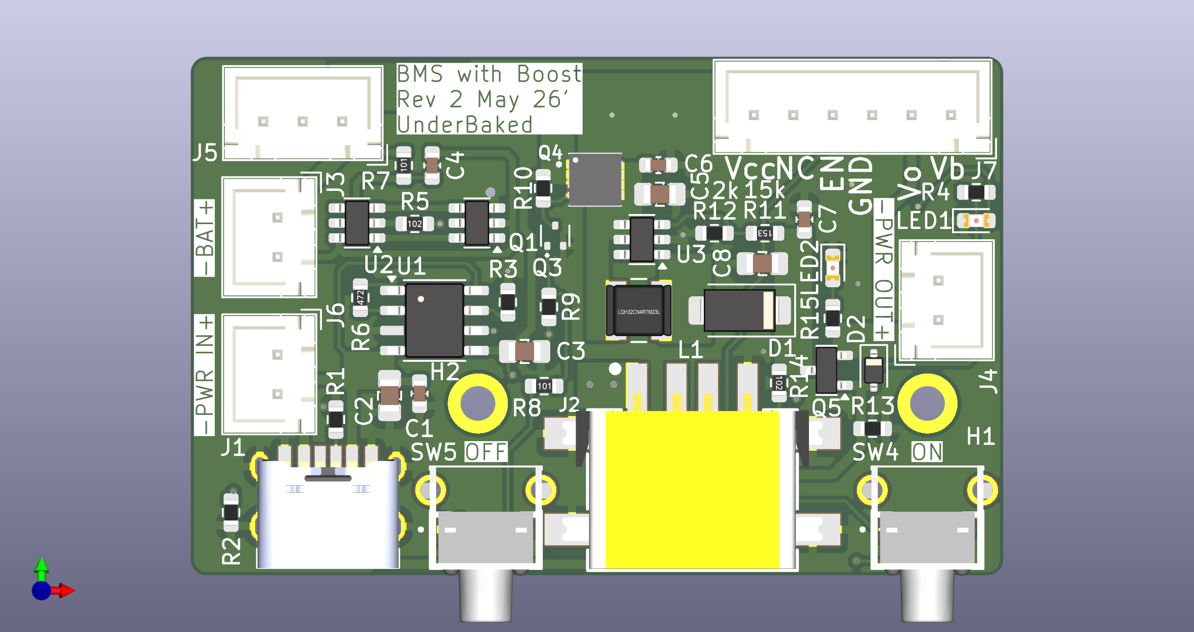
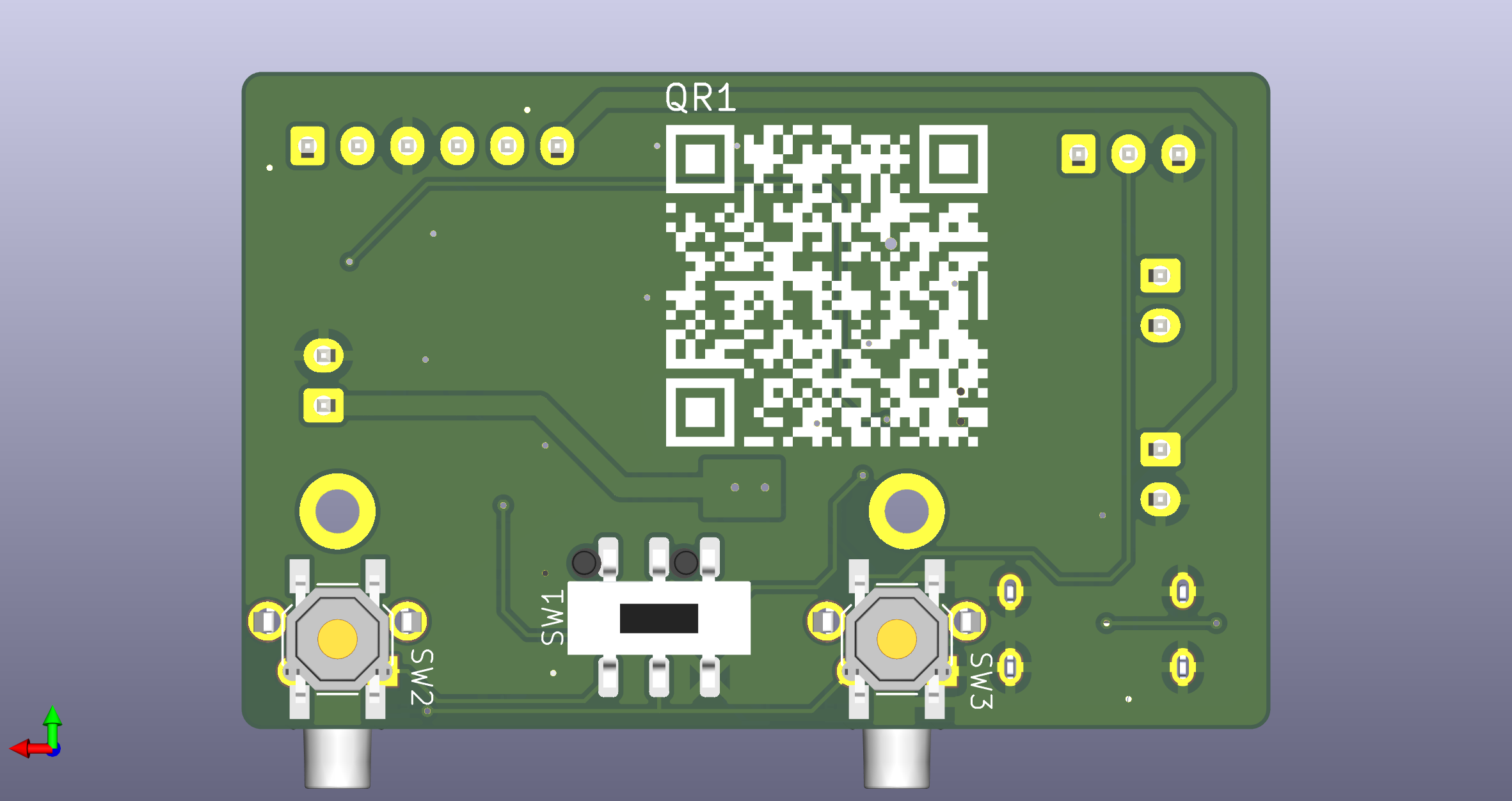
Refer to board images:
Key Components:
- U1, U2: BMS chips (left side)
- U3: Boost converter IC (right side)
- L1: Inductor (center-right, black component)
- J2: USB-C port (center-bottom)
- SW4, SW5: Switches (if populated on top)
- SW2, SW3: Alternative switches (if populated on bottom)
Testing BMS (without battery):
- Measure resistance across battery connector terminals
- Should not be dead short
- Typical: TODO kΩ
Testing Boost Converter (with battery):
- Connect battery only (no output load)
- Measure Vcc test point - should be ~5V
- Enable boost converter (via switch if applicable)
- Voltage should remain stable
Testing Charging Circuit:
- Connect battery
- Connect USB-C power (5V)
- Charging LED should indicate charging (if battery not full)
- Measure charging current if possible (TODO mA typical)
- Immediately disconnect all connections
- Move to fireproof container
- Monitor for swelling or smoke
- If smoking: evacuate area, call fire department
- Do not attempt to charge hot battery
- Allow to cool completely before investigation
- Immediately remove power
- Disconnect battery
- Do not reconnect power
- Inspect for:
- Burnt components (discoloration)
- Damaged traces
- Shorted components
- Contact support - board may need replacement
- Polarity likely reversed
- Immediately disconnect
- Inspect connector and cable for damage
- Verify polarity before reconnecting
- Check for damage to board components near connector
No power at all:
- Check battery voltage → If low: charge battery
- Check connections → If loose: reseat connectors
- Check polarity → If reversed: correct polarity
- Check test points → If no voltage: board fault
Power but no 5V output:
- Check Vb test point → If low: charge battery
- Check switches → If off: enable output
- Check load → If excessive: reduce load
- Check Vcc test point → If no voltage: boost fault
Won't charge:
- Check USB-C connection → If loose: reseat
- Check battery voltage → If full: normal behavior
- Check charging LED → If not lit: verify USB power
- Check Vb test point → If increasing: charging OK
Stop immediately and seek expert help if:
- Battery is swollen, leaking, or damaged
- Components are smoking or have burned smell
- You detect any signs of fire or thermal runaway
- Battery temperature exceeds TODO °C
- You are unsure of the problem
If you've tried these troubleshooting steps and still need help:
- Review the Assembly Instructions for proper construction
- Check the Bill of Materials for correct component values
- Review Safety Guidelines
- Visit the Support section for additional help
⚠️ Important: When requesting support, provide photos of your assembly and multimeter readings.
Last Updated: TODO
Revision: See Revision Notes